|
|
|
1. Pipes
carrying water (smooth bore pipes)
|
 A
spreadsheet is available for download here which will perform the friction
loss calculation for you.
A
spreadsheet is available for download here which will perform the friction
loss calculation for you.
|
|
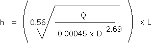
To calculate the flow down a pipe, knowing the
headloss : Q = 0.00045 x D2.69 x H0.56
|
|
Where Q = flow in litres per second
D - Internal diameter of pipe in millimetres
H = Hydraulic gradient = Metres headloss of pipe (h)
Metres
of pipelength (L)
|
|
Changing this equation round, the headloss can be
calculated if the flow required is known;
This is fine for individual lengths of pipe with no
fittings, but pipe system are rarely like this, the table below
gives an equivalent pipe length to each fitting, and by adding the
sum of all the “equivalent lengths” form the fittings and the
total pipe length, the above equation can be used to calculate the
friction loss (or headloss):
|
|
Fitting
|
Equivalent
Pipe Length
e.g. 30D = 30 x diameter of pipe
|
|
90 degree elbow
|
30D
|
|
45 degree elbow
|
20D
|
|
T straight through
|
16D
|
|
T through side
|
60D
|
|
Swept 90 bend
|
4-8D
|
|
Open gate valve
|
9D
|
|
Open globe valve
|
275D
|
|
Full bore non return valve
|
6D
|
|
Butterfly valve
|
20D
|
|
There are also other methods for calculating
friction losses in pipes but the above is the simplest. The headloss
figure that is gained form the above calculation can then be used to
specify pumps, or the height of the header tank required.
|
|
|
|
|
|
2. Channels
|
|
|
|
The amount of water which flows down a channel is a
function of the cross sectional area, the wetted perimeter, the water velocity, the gradient of the channel
and the coefficient of
roughness of the channel.
|
|
|
|
|
|
|
Coefficient
of roughness of common materials
|
|
|
|
Glazed and very smooth surfaces
|
0.010
|
|
|
Cement plaster, iron and other smooth pipes in good
condition
|
0.011
|
|
|
Concrete sewers >1500mm diameter
|
0.012
|
|
|
Concrete sewers 600 - 1500mm diameter
|
0.013
|
|
|
Brick sided, concrete based channels
|
0.015
|
|
|
Coarse brick, earth in good order channels
|
0.020
|
|
|
Earth canal in reasonably good condition, free of
stones and weed
|
0.025
|
|
|
Earth canal in poor condition, with some stones and
weed
|
0.030
|
|
|
|
|
|
|
Calculation Q
= (1/n x ((A x WP)2/3) x S1/2) x A
Where:
Q = Flow rate m3/sec
n = Coefficient of roughness
(see above)
A = Cross sectional area of channel (m2)
WP = Wetted perimeter of channel (m)
S = Gradient of channel (m). Metres per 100m. e.g.
if the channel falls
0.5m every 100m, S=0.5
See also Channel,
Limiting velocity and Scouring velocity for other design
criteria which must be considered.
|
|
|
|